
Diaphragm Metering Pump: Complete Guide
Table of Contents
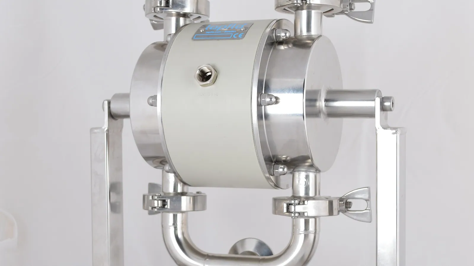
The diaphragm metering pump is the most common chemical dosing pump in the world. It dominates water treatment, cooling towers, pools, boiler chemical programs and a large share of industrial chemical injection. Its popularity comes down to one property: the pumped chemical never touches the drive mechanism. That makes it leak-tight by design, easy to service, and cheap to maintain with a small set of consumable parts.
This guide covers how diaphragm metering pumps work, the solenoid-vs-motor decision, diaphragm materials, the parts that wear out, and how to buy compatible replacements for the major brands.
What Is a Diaphragm Metering Pump?
A diaphragm metering pump is a positive-displacement pump in which a flexible diaphragm — usually PTFE-faced — flexes to displace a precise volume of chemical per stroke. The diaphragm sits between the chemical (wetted) side and the drive side, so the motor, gears and bearings never contact the process fluid.
Output is set by stroke length and stroke frequency. A typical solenoid model delivers 0.5–30 L/h at up to 10–30 bar; motor-driven models reach hundreds of L/h and higher pressures. Accuracy is typically ±1–2%, sufficient for almost every dosing duty.
How a Diaphragm Metering Pump Works
One complete cycle moves one fixed volume:
- Suction: the diaphragm retracts, chamber volume increases, pressure drops. The suction check valve (a ball-and-seat or cartridge valve) opens and liquid enters.
- Discharge: the diaphragm advances, pressure rises. The suction valve closes, the discharge valve opens, and the liquid is pushed into the process line.
The diaphragm is flexed by one of two drive mechanisms:
- Mechanical actuation: an eccentric cam pushes the diaphragm directly (or via a connecting rod). Simple, robust, common in motor-driven pumps.
- Hydraulic actuation: the diaphragm is pushed by hydraulic oil behind it. This gives smoother motion, higher pressures, and longer diaphragm life — used in large industrial pumps.
- Solenoid actuation: an electromagnetic coil pulls a plunger that flexes the diaphragm once per electrical pulse. Stroke rate is set by pulse frequency.
The two check valves are the heart of the liquid end. When they wear or stick, the pump loses prime, output drops, or flow becomes erratic — the most common failure modes in the field.
Solenoid vs Motor-Driven Diaphragm Pumps
| Criterion | Solenoid diaphragm | Motor-driven diaphragm |
|---|---|---|
| Flow range | 0.5 – 30 L/h | 1 – 500+ L/h |
| Pressure | up to 10 – 30 bar | up to 50 bar (hydraulic: 200+) |
| Accuracy | ±2% typical | ±1% typical |
| Power | Low (pulses on demand) | Continuous motor |
| External signal | Pulse input (flow meter, PLC) | 4–20 mA, frequency drive |
| Ideal for | Pool, small chemical dosing, remote solar sites | Industrial water treatment, boiler, continuous process |
Solenoid pumps are the workhorses of pool and light commercial dosing — cheap, efficient, and easy to control from a flow meter pulse. Motor-driven pumps are the industrial standard where flow and pressure demands are higher. Hydraulic-diaphragm versions add a layer of cost and complexity but deliver the smoothest, most accurate output at high pressure.
Key Specifications
- Flow at max stroke (L/h): the rated number, usually at water and mid-pressure. Actual flow with viscous or dense chemicals differs.
- Max discharge pressure (bar): the back-pressure limit. Do not oversize pressure — it costs money and stresses the diaphragm.
- Stroke length and rate: volume per stroke and strokes per minute. Turndown is typically 10:1; run at 30–90% stroke for optimum accuracy.
- Diaphragm size and material: the single most important spare part. Match to the model series.
- Input options: manual, external pulse, 4–20 mA, or network control — choose based on how the pump is integrated.
Diaphragm Materials Explained
| Material | Properties | Typical Use |
|---|---|---|
| PTFE (Teflon) faced | Excellent chemical resistance, low friction; not elastomeric, so usually laminated over EPDM/NBR backing | Aggressive chemicals: hypochlorite, acids, solvents — the default |
| EPDM | Good resistance to water, mild chemicals, ozone; poor with oils and hydrocarbons | Water treatment, mild chemicals, economical choice |
| Viton (FKM) | Resists oils, fuels, aromatic solvents; poor with ketones and hot water | Oil & gas, hydrocarbon service |
| Hypalon (CSM) | Resists strong oxidizers, acids, ozone | Hypochlorite and oxidizer dosing |
| Santoprene / TPV | Good chemical balance, longer flex life | General industrial dosing |
Most modern pumps use a PTFE-faced diaphragm with an elastomer backing: the PTFE face takes the chemical, the elastomer layer provides the flex. When buying a compatible diaphragm, verify both layers match the OEM spec — a diaphragm with the right shape but the wrong backing material will fail early.
Common Applications
- Pool and spa chlorine/pH dosing — solenoid pumps with EPDM or PTFE heads.
- Municipal and industrial water treatment — coagulant, flocculant, chlorine, pH adjustment.
- Cooling tower chemical programs — biocide, scale and corrosion inhibitor.
- Boiler water treatment — phosphate, amine, oxygen scavenger dosing.
- Wastewater — polymer and chemical dosing for clarification.
- Agriculture and fertigation — nutrient and acid dosing in irrigation.
- Food processing — CIP and additive dosing with sanitary heads.
Diaphragm Failure: Symptoms, Causes, Replacement
Symptoms of a failing diaphragm:
- Output drops below setpoint even after re-priming.
- Chemical appears in the drive housing or oil (hydraulic pumps).
- The pump runs but delivers erratic or pulsing flow.
- Visible pinholes, cracking, or deformation when inspected.
Common causes:
- Normal flex fatigue — diaphragms are consumables with a finite life (typically 12–24 months).
- Running against debris or abrasive particles in the chemical.
- Chemical attack from an incompatible material or concentration.
- Running the pump dry or against a blocked discharge, over-flexing the diaphragm.
- Excessive stroke rate at high pressure, generating heat.
Replacement procedure (typical liquid end):
- Isolate and depressurize the pump; drain the head.
- Remove the head bolts and take off the liquid end (the housing holding the diaphragm and valves).
- Remove the old diaphragm; clean the seat area.
- Fit the new diaphragm, ensuring correct orientation and torque per the manual.
- Reinstall valve cartridges (or replace them at the same time — they wear together).
- Reassemble, re-prime, and run a calibration check.
Replacing the diaphragm and valve cartridge together is the industry-standard service interval — that is exactly what a preventive maintenance kit (PMK) contains.
Valve Cartridges and the Liquid End
The liquid end consists of the head, the diaphragm, and two check-valve assemblies (suction and discharge). Valve cartridges contain the ball and seat — typically ceramic or glass balls in PTFE/PVDF seats. They fail from:
- Crystallization: chemicals like sodium hypochlorite and ferric chloride leave crystals that jam the ball.
- Debris: unfiltered product or tank sludge seats the ball unevenly.
- Wear: abrasive chemicals erode the seat, causing internal leakage.
When flow becomes erratic, check the valve cartridges before the diaphragm — they are cheaper, faster to swap, and the most common culprit. Keeping a spare cartridge set on the shelf solves most "pump not dosing" calls in minutes.
Compatible Diaphragms: LMI, ProMinent, SEKO and More
Diaphragms and valve cartridges are specified by pump series, not just brand. The major installed base breaks down as:
- LMI (now Milton Roy / Flowserve): A, B, C, D, E series — solenoid liquid ends with PTFE-faced diaphragms and ceramic-ball cartridges.
- ProMinent: Gamma/L, Concept, EXTRONIC, delta — various head sizes and materials.
- SEKO: Tekna, Kompact, Sprint, KCL — PVDF/PP heads, ceramic balls.
- Milton Roy: mRoy, Milroyal, Centrac — motor-driven, hydraulic diaphragm options.
- Pulsafeeder: Pulsatron (solenoid), Chem-Tech — widely installed in water treatment.
- Walchem / Iwaki: EWN, EZG series — solenoid and motor metering.
A quality compatible-parts supplier stocks diaphragms, valve cartridges, PMK kits, seals and o-rings for these series, cross-referenced by pump model. Before ordering, confirm: pump series, head material, and diaphragm material. When in doubt, send the pump model or the old part — a good supplier matches it for free.
FAQ
How long does a diaphragm metering pump diaphragm last?
Typically 12–24 months in normal chemical service. Aggressive chemicals, high pressure, high stroke rate and abrasive contamination shorten life. Inspect at every service interval.
Can I replace just the diaphragm, not the whole pump?
Yes — the diaphragm is a consumable part. This is the standard maintenance practice and the reason compatible diaphragms are widely stocked.
My pump is pulsing but delivering less chemical. What's wrong?
Most likely a worn or stuck valve ball in the liquid end, or a failing diaphragm. Check the valve cartridges before the diaphragm.
Are compatible diaphragms as good as OEM?
A compatible diaphragm with matching material and dimensions performs to the same standard. The key is verifying the PTFE facing and elastomer backing match the OEM spec.
What is a PMK kit?
A preventive maintenance kit — diaphragm, valve cartridges, o-rings and seals for one service interval, bundled for a specific pump model. Keeping one on the shelf avoids emergency sourcing.
Installation Essentials: Suction, NPSH and Piping
How a diaphragm metering pump is piped decides how reliably it doses. Most field problems — air locks, erratic output, cavitation, siphoning — are installed-in rather than manufactured-in. Two rules prevent the majority of them: give the suction side a continuous liquid supply, and keep the discharge side under stable, controlled back-pressure.
Suction side. Flooded suction is the preferred arrangement: the chemical tank sits above the pump inlet so liquid flows into the head by gravity. Where that is impossible, a suction lift of 1.5–3 m is achievable with a solenoid or small motor pump in water-like service; beyond that, output becomes unreliable because the pump must overcome lift, pipe friction and fluid vapor pressure simultaneously. The pump's NPSH requirement (net positive suction head) must be covered by the head available at the inlet — a flooded tank gives the full liquid level as margin, while a lifted line consumes that margin before the pump sees any of it. Keep the suction line short, direct, and one size larger than the pump connection, with no high loops where gas can collect.
Discharge side. Work back from the injection point and fit these in order:
- Injection quill at the injection point so the chemical enters the center of the process line, plus a spring-loaded check valve that stops process fluid from back-flowing into the pump while it is off.
- Back-pressure valve where the discharge line is open-ended or the injection point sits far below the pump — without one, flooded head pressure or a long vertical drop can siphon chemical through the pump after shutdown.
- Pulsation dampener close to the pump on the discharge — solenoid pumps pulse at roughly 10–120 strokes per minute, and those pulses hammer fittings, disturb flow-meter readings and cause valve chatter.
- Relief valve set at or just above the rated pressure — a closed block valve or a crystallized injection point can otherwise dead-head the pump past its limit.
- Suction strainer or foot valve on the tank side, typically 60–100 mesh, to keep debris and polymer skins out of the valve cartridges.
Injection point placement. Inject where pressure in the process line is stable — downstream of pumps and control valves — and at a point of turbulence such as after an elbow or a static mixer, so the chemical mixes instead of stratifying. Keep the injection point away from pH, ORP or chlorine sensors that would read undiluted chemical, and respect the head material's temperature limit: plastic heads are generally rated to roughly 40–50 °C continuous, so hotter lines need a cooling arrangement or a stainless head. Where several chemicals inject into one line, space the points apart and check for cross-reactions at the contact point.
How to Calibrate a Diaphragm Metering Pump
Stroke length on a diaphragm metering pump is a percentage, not a flow guarantee. Actual delivered volume depends on line pressure, chemical viscosity, valve condition and how well the pump stays primed — which is why working installations, and most water-treatment compliance programs, rely on regular calibration rather than trusting the dial. A complete check takes about ten minutes and a graduated cylinder.
Method 1 — calibration column on the suction side. Many chemical tanks are built with a calibration column or a graduated sight tube; the same logic works with a clear PVC tube fitted to the suction line.
- Fully prime the pump and run it at operating pressure for 2–3 minutes so the head and valves settle.
- Close the tank supply so the pump draws from the column, and note the starting level.
- Set the working stroke length and stroke rate, then time a measured run of 60 seconds.
- Read the level drop and convert it to volume: level drop (mm) × column cross-sectional area = mL delivered.
- Compare the measured mL/min with the theoretical value from the pump's flow curve at that stroke and discharge pressure.
Method 2 — stopwatch and graduated cylinder on the discharge. Where no column is available, discharge into a 100–1000 mL graduated cylinder:
- Prime and stabilize as above, with the discharge line open to the process or to a drain.
- Start the stopwatch as soon as liquid reaches the cylinder and time 60 seconds — longer at very low flows.
- Read the collected volume, multiply by 60 for mL/h, then divide by 1000 for L/h.
- Repeat twice and average the readings; a single run is not evidence of accuracy.
Working out the error and correcting it. Error % = (measured − theoretical) ÷ theoretical × 100. Acceptance is typically ±2% for motor-driven pumps and ±5% for solenoid pumps at low flow. If you are outside that window, adjust the stroke length in the same proportion as the error and re-measure — a 10% dial error compounds over a full year of dosing. Record the date, stroke setting, measured flow and error in a log; the trend line reveals a diaphragm or valve wearing out before it actually fails.
When to calibrate: at commissioning; after diaphragm or valve cartridge replacement; after any change of chemical or concentration; quarterly in routine service; and immediately when process tests (residual chlorine, pH, ORP) drift even though the dial has not moved.
Brand Series Compared: LMI, ProMinent, SEKO Liquid Ends
Diaphragms and valve cartridges are specified by pump series, not by brand name, and the same brand spans several different liquid ends. Three families cover most of the installed base. The differences that matter for spare parts are head material, diaphragm diameter and construction, and ball and seat material. Flows below are approximate water ratings at maximum stroke — verify the exact numbers on the pump nameplate before ordering.
| Series | Drive | Typical flow (water, max stroke) | Typical pressure | Liquid end characteristics |
|---|---|---|---|---|
| LMI A series | Solenoid | up to ~30 L/h | 10–30 bar class | PVC, PVDF or 316SS head; PTFE-faced diaphragm over elastomer backing; ceramic ball with PTFE seat; 1/4"–1/2" connections |
| LMI B, C, D, E series | Solenoid | roughly 95 / 190 / 380 / 950 L/h stepping by series | 10–30 bar class by model | Same valve architecture with larger diaphragm diameters; the series letter on the nameplate defines the spare part |
| ProMinent Gamma/L and Gamma/X | Solenoid | roughly 2–32 L/h | up to ~16 bar | PVDF, PVC, PP or stainless head; PTFE diaphragm with EPDM backing; ceramic ball, PTFE seat; G 1/4 threaded connections typical |
| ProMinent Concept | Motor-driven | roughly 0.5–33 L/h | up to ~10 bar | Compact motor liquid end; PTFE-faced diaphragm; ceramic ball assemblies; several head sizes by model |
| SEKO Tekna series | Solenoid | roughly 1.5–20 L/h | up to ~10 bar | PVDF or PP head; PTFE diaphragm; ceramic ball; 1/4"–3/8" connections; degassing head option for hypochlorite duty |
| SEKO Kompact and KCL | Motor-driven | roughly 1–20 L/h (Kompact), up to ~90 L/h class (KCL) | up to ~16 bar | Motor liquid ends with the same PTFE-diaphragm and ceramic-ball architecture; larger heads on KCL |
The practical consequence: two pumps from the same brand can require different diaphragms, because the liquid end — not the logo — defines the part. An LMI B-series diaphragm will not fit an A-series head even though the valve cartridges look similar, and a SEKO Tekna cartridge set differs from the Kompact set. Order with the full model or type code from the nameplate plus the head material; that is what a supplier cross-references to the correct diaphragm diameter, ball size and o-ring set.
Preventive Maintenance Schedule: Monthly, Quarterly, Annual
A diaphragm metering pump has a short list of wear parts and a long service life when they are changed on schedule. The standard service package — the preventive maintenance kit (PMK) — bundles the diaphragm, both valve cartridges, o-rings and seals for one pump model. The schedule below is a working baseline for continuous water-treatment duty: a 24/7 plant with aggressive chemicals should shorten the intervals, and a seasonal pool installation can stretch them.
| Interval | Checks | Replacements and actions |
|---|---|---|
| Monthly | Leak check on head and fittings; stroke setting vs. log; suction strainer; injection point and back-pressure valve; tank level and chemical condition | None planned — clean the strainer if fouled; clear any crystallized chemical around the valves |
| Quarterly | Calibration check (column or cylinder method); valve cartridge inspection — ball seating, crystal build-up, wear; suction line for air pockets; oil level on motor-driven models; discharge pressure vs. rated | Fit a clean cartridge set if balls are pitted or seats show wear; keep the removed set as emergency spares until rebuilt |
| Annual or every 12–24 months | Full liquid-end overhaul: head inspection for corrosion and scale; diaphragm condition; o-ring sealing surfaces; drive check (solenoid coil, motor gearbox) per the manual | PMK install — new diaphragm, valve cartridges, o-rings and seals; new suction strainer element; full re-prime and calibration after reassembly |
Two habits separate plants with reliable dosing from plants with surprise failures. Keep a running log: stroke setting, measured output, calibration results and any part swap. The log turns a "sudden" flow loss into a predictable trend — output drifting a few percent over months points at valve wear, while a sharp drop points at a stuck ball or air in the line. Alongside the log, service the liquid end as a set: when the diaphragm comes out after 12–24 months, the valve cartridges are near the end of their life too, and reusing them on a fresh diaphragm only defers the next failure by a few weeks.
Diaphragm vs Peristaltic vs Plunger Pumps: How to Choose
Diaphragm pumps dominate chemical dosing, but they are not the only positive-displacement option. Peristaltic (tube or hose) pumps and plunger (piston) pumps each win in specific duties. The table below compares the three on the criteria that drive real selection decisions.
| Criterion | Diaphragm pump | Peristaltic pump | Plunger / piston pump |
|---|---|---|---|
| Dosing accuracy | ±1–2% typical | ±2–5% — drifts as the tube wears | ±0.5–1% |
| Max pressure | 10–50 bar typical; hydraulic-diaphragm versions to 200+ bar | Up to ~10–15 bar; most duty below 7 bar | Up to 300+ bar |
| Flow range | 0.5 L/h to hundreds of L/h | mL/h to ~500 L/h class (hose pumps higher) | L/h to m³/h class |
| Leak-tightness | Sealed by the diaphragm — no dynamic seal on the wetted side | Sealed by the tube — fully closed system | Packing or mechanical seal; slight seepage is normal with packing |
| Viscous fluids | Limited — viscosity affects valve behavior above roughly 500–1000 cP | Handles viscous and shear-sensitive fluids well | Good with viscous fluids when valves are sized correctly |
| Abrasives / slurries | Poor — abrasive particles attack valves and diaphragm | Good — the tube tolerates abrasives | Poor — abrasives destroy packing and plunger |
| Dry-run tolerance | Poor — running dry over-flexes and overheats the diaphragm | Good for short periods | Poor — damages packing |
| Consumables | Diaphragm and valve cartridges every 12–24 months | Tube or hose every weeks to months by duty | Packing, plunger and valves |
| Typical fit | Water treatment, chemical dosing, boiler and pool programs | Slurries, abrasives, pharma and shear-sensitive dosing | High-pressure, high-flow, clean fluids such as boiler feed and refinery injection |
Practical decision rule: if the fluid is clean and the duty is dosing, choose the diaphragm pump. If the fluid carries solids or must not be sheared, choose peristaltic. If the duty is high-pressure, high-flow and clean, choose plunger. Diaphragm pumps remain the default wherever leak-tightness and easy servicing matter more than absolute accuracy — which is why water treatment, pools and boiler programs run on them almost exclusively.
Building Your Spare Parts Kit
Every diaphragm metering pump will need parts eventually, and the difference between a 20-minute repair and a two-day shutdown is whether the parts are already on the shelf. For each pump model in your plant, stock one complete service set:
- Diaphragm matching the exact series and head material — PTFE-faced, over the correct elastomer backing.
- Valve cartridge set — suction and discharge, balls and seats together.
- O-ring and seal kit for the head.
- Spare suction strainer element and, where fitted, a spare back-pressure valve spring.
Label each set with the pump model and head material so any technician can grab the right kit without reading the manual. When ordering, a photo of the nameplate — or of the old diaphragm — is the fastest way to guarantee a match: send the model code and head material, and a competent supplier cross-references the rest. PMK kits bundle the items above into one stock-keeping unit; if you run a fleet of the same model, the standard practice is one PMK per pump on the shelf.
NEXT STEP
Need the Right Metering Pump Part?
Send us your pump model — our team matches the correct part and responds within 24 hours.
Written by
Ray ChanMetering pump parts specialist. Ray helps water treatment plants, chemical plants and maintenance contractors source factory-direct compatible pump parts.